When I picked up this small photo of a large monstrosity, there were two things that I realized right away: the print was damaged, and I had no clue what plane it showed. My friend and photo restoration artist Bob Cohen took a stab at it, and took care of both problems...so below is the restored image, and he was able to come up with an identity, a Blériot 74 (or in Blériot's parlance, an LXXIV)...or is it?
After doing some more checking, it turns out that this is one of those murky corners of aviation history where things don't always make a lot of sense, and there are a whole lot of places on the internet where not a lot of care has gone into accuracy in image captions. Here's some of what I found in digging into this little mystery.
First, Frenchman Louis Blériot was the fellow who invented the first practical automobile headlamp. With that invention bringing a nice steady flow of cash, he could delve into his real passion, aeroplanes. In 1909, he hit the jackpot (in fame at least), and developed the world's first successful monoplane, the Type XI, and then used it to become the first person to fly across the English Channel, claiming the Daily Mail's £1,000 prize. His company produced around 900 airplanes, most of them based on the type XI. He later came to head a consortium called the Société pour les Appareils Deperdussin, which he renamed Société Pour L'Aviation et ses Dérivés, better known by its acronym SPAD.
At some point during WWI, Blériot started thinking big, really big. Bomber big. The results of this thinking took the form of five large one-off aircraft, the Type 67, 71, 73, 74 and 75. The first four were intended to be large, long-range bombers, and the last was to be an airliner variant based on the airliners. None of these planes were successful by any means. One of these planes is shown in the photo above, but figuring out which has proved to be harder than I expected, so I'll run through them here.
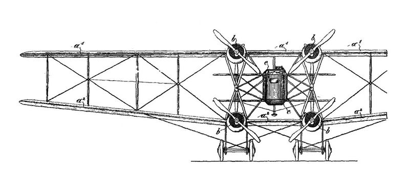
The first, the Type 67, is the one that, structurally, most resembles the plane in our photo, with a fuselage suspended between both wings. However, the Type 67 used Gnome rotary engines, and flew only once, on September 18, 1916, crashing at the end of the flight. By now, you've probably noticed the "67" written by hand in the lower right corner of our photo. Was this an indication of the subject, or just a negative number (which would be an odd coincidence)? The issue is, of course, that this photo clearly doesn't show the plane to be powered by rotary engines. Maybe Blériot started out with inline Hispano-Suizas and then changed his mind? Then I found this patent drawing of the Type 67 on a Russian web page called Their Flying Machines. While photos of the 67 clearly show Gnome radials (this one, for instance), the drawing shows the smaller cowlings that were used over the in-line engines shown in our photo.
Blériot's next attempt was the slightly larger Type 71 which debuted in November 1917, but the patent drawing for this one (which comes from this Blériot page on the Arizona Model Aircrafter's website) shows a fuselage, though similar in shape to the 67, now mounted directly on the lower wing.
The Type 73, an even stranger aircraft, followed in 1918, but was destroyed when it broke up in-flight on January 22, 1919. Here's its patent drawing...clearly not our bird. A second Type 73 had been started, but after the crash of the first one, that attempt was abandoned, and the wings, which had already been built, were used on the Type 74, a whale of a plane. And then there was the 75, the airliner version. Thankfully it was also abandoned.
So, for our photo, my money is on the Type 67, which at one point or another was equipped with different engines than it eventually flew with. Have a different thought or opinion? I'd love to hear from you via the comments section below.
Showing posts with label Epic Fail. Show all posts
Saturday, February 14, 2015
Friday, December 26, 2014
Legend of the Lame Loon
This is the Loon, a first experiment in developing what, at the time, was called a hydroaeroplane. It failed miserably, never becoming airborne and eventually sinking. But sometimes, failure spurs further development and research, and ultimately leads to success. And of course, it also leads to a really good story (and several digressions).
When most people think of Alexander Graham Bell, they naturally think of the telephone, with which he is credited as inventor. However, Bell was responsible for so much more, and aeronautics was one of his biggest passions. To a certain degree, he can be credited with ensuring that the world of American aeronautics was not dominated by two monopolizing brothers from Dayton, Ohio.
Bell's personal secretary had a son, J. A. Douglas McCurdy, who had just recently graduated with an engineering degree. Being close to the Bell family, Douglas one day invited his close friend and classmate Frederick "Casey" Baldwin over to the Bell's for dinner and a discussion on aeronautics. Alexander Bell's wife, Mabel, suggested that the three men establish a research society in order to collaborate and experiment in aeronautics. Since Mabel was independently wealthy through real estate investments, she offered to finance the endeavor with a fund of $35,000 (almost a million, in today's dollars). They called the collective the Aerial Experiment Association, and it was officially established on September 30, 1907; Bell later described it as a "co-operative scientific association, not for gain but for the love of the art and doing what we can to help one another."
The airplanes they hoped to build would need engines, so the group approached Glenn H. Curtiss, who had made a name for himself by developing gasoline engines, and had became famous as "the fastest man on earth" when he had ridden his V-8 engine-powered motorcycle to an unofficial world speed record of 136 mph in 1907. Curtiss had also realized that aviation was the future, and had offered one of his engines to the Wright Brothers, only to be rebuffed; they had their own engine design, thank you very much. Curtiss thus readily accepted membership with the AEA.
Understanding that the government would likely be very interested in the new developments in aeronautics, Bell became aware of Army Lt. Thomas Selfridge's interest in the technology, and wrote a personal letter to President Teddy Roosevelt asking if Selfridge could be assigned to participate in the AEA. Teddy was more than happy to accommodate the request, and the AEA was then five.
Since the AEA was intended as a non-commercial scientific endeavor, they also solicited input from other inventors, and the Wright Brothers as well as Octave Chanute willingly shared some of their experimental design data. The AEA's first project was an unpowered hang-glider based on some of Chanute's design knowledge. Subsequently, the AEA group built five aircraft, each having a different one of the five principal AEA members as its chief designer.
The first was a plane designated Aerodrome #1, and named the Red Wing, designed by Selfridge (the name came from the red silk used for the wings, and oddly, the color red was chosen because it would look the best in a black and white photograph). On March 12, 1908, with Baldwin at the controls, the Red Wing took off from the ice of frozen Keuka Lake, new Hammondsport, NY, flew 319 feet, reached an altitude of 200 feet. The flight was heralded as the first public flight in the US (all of the Wright Brothers' US flights had been done in secret), and the first flight piloted by a Canadian citizen. Then, during a second flight on March 17th, it crashed, damaged beyond repair.
The AEA's second project, Aerodrome #2, built on the lessons learned. It was designed by Baldwin and called the White Wing. The design incorporated a number of innovations, including using wheels for its landing gear, and ailerons championed by Bell for roll and directional control (more on this a bit later in the story). First flight, with Baldwin at the controls, took place on May 18, 1908; unlike the Red Wing, this one flew quite well. The following day, Selfridge flew it (becoming the first US military pilot), and on the 20th, Curtiss took it into the air with a flight of 1,017 feet. Two days later, on the 23rd, McCurdy flew it but crashed on landing. It, too, was beyond repair.
Aerodrome #3 was designed by Curtiss, and again took advantage of lessons learned. The team had their eyes set on the $2,500 Scientific American Cup, a prize offered for the first aircraft to make a public flight of one kilometer (3,280 feet, or about three times farther than the White Wing flew). Named June Bug by Bell for the ochre color of its coated silk wings, the resemblance to the insect and the month of its completion, it first flew on June 21st, and between then and the 25th made five flights with Curtiss at the controls, each progressively longer, the last being 3,420 feet. Buoyed by these successes, the team contacted the Aero Club of America and requested the opportunity to fly for the prize. In an attempt at fairness, the Aero Club asked the Wright Brothers if they wanted to attempt the record first, but they declined saying that they were too busy preparing for a government demonstration flight. So, Curtiss was given the opportunity to fly on July 4th, and a huge crowd gathered to watch the spectacle. After one false start, Curtiss easily exceeded the measured course, covering 5,360 feet in one minute, forty seconds, clinching the prize.
Then, on September 17th, the 26-year-old Selfridge was riding as a passenger with Orville Wright as the Wright Flyer was demonstrated for the Army Signal Corps, when the right propeller broke and the subsequent damage led to the crash of the plane. Neither man wore any kind of safety restraint, and both were violently thrown forward in the impact. Wright was badly injured, and Selfridge suffered a skull fracture, passing away several hours later after an unsuccessful surgery; he thus became the first person in history to be killed in an airplane crash. He had not been wearing any head protection, and as a result, the Army specified that their pilots would henceforth wear helmets.
The AEA team mourned his loss, but continued their development. Bell and Curtiss had both been intrigued by the idea of flying a plane from water rather than land, so decided to modify the June Bug with twin pontoons. The modified plane was re-christened the Loon and testing began on November 28th on the 20-mile-long Keuka Lake, one of New York's Finger Lakes. Try as they might, though, the team could not get the Loon to exceed 29 mph, and at that speed it couldn't break free from the water and become airborne. The AEA team continued to try until on January 2, 1909, one of the pontoons was damaged and the plane sunk. Though it was recovered, no more attempts were made, and the Loon eventually rotted away while stored in a nearby boathouse.
The failure of the Loon to get airborne was the result of one rapidly-progressing technological discipline, aeronautics, running head-on into the limitations of another, hydrodynamics. As soon as the AEA team bolted on the floats, they entered a different world, and had two areas of engineering to deal with. To understand the challenges, we need to digress for a moment and talk about boats (this will be a general overview...if you want a bit more technical of an explanation, jump down to the engineering notes at the bottom of this article). As a boat, say your average rowboat, sits in the water, it is held afloat by buoyancy, one of two forms of water-related "lift" that a boat can experience. As the rounded hull (known as a displacement hull) moves through the water, it has to shove a whole bunch of water aside and ahead of it, and that creates a whole bunch of drag, called wave-making drag. In addition, the boat also experiences friction drag from the hull interacting with the water over what's known as the "wetted" area. As the boat moves faster, the drag increases significantly, meaning that ever-increasing amounts of power are required for even small increments of additional speed. In addition, such displacement hulls have a tendency to tuck under if too much power applied.
The second type of lift is what's known as "planing" or "hydroplaning", in which the boat is supported by the dynamic lift provided by the water rather than its buoyancy. It's not unlike part of the lift experienced by an airplane's wing. If a boat is properly designed and can reach the point (and speed) where it is planing, it will no longer tend to tuck under, but instead the nose will pitch higher and higher as the center of lift (aka dynamic pressure) moves aft with increased speed.
What doomed the Loon to failure was the fact that it used two very thin, knife-like pontoons, and so all of its water-derived lift was displacement, and as the pilot tried to accelerate to the speed where the wings would produce enough lift to fly away, the water drag would increase dramatically, and tuck-under would start to happen. In the parlance of the day, the AEA team described it as not being able to become "unstuck" from the grip of the water.
The AEA went on to build two more land-based aircraft, the successful McCurdy-designed Silver Dart which first flew on February 23, 1909, and the highly unorthodox and unsuccessful Bell-designed Cygnet II, which was not able to get airborne. By this point, Curtiss saw the commercial potential for aeroplanes, and partnered with August Herring to form the Herring-Curtiss Company in late March. This led, ultimately, to the dissolution of the AEA. Curtiss purchased the design rights to Aerodrome #3, and modified it to become the Curtiss No. 1 (aka Curtiss Gold Bug, aka Curtiss Golden Flyer), with which he again won the Scientific American Cup in 1909.
Despite the failure of the Loon, Curtiss and Bell hadn't given up on the idea of water-borne flight. The lakes, rivers and oceans presented, as Curtiss saw it, a lot more places to fly from than land, with a lot few obstacles. An article in the March 1906 issue of Scientific American by William Meacham on the principles of hydroplaning had intrigued Bell, and he and Baldwin did some experiments in 1908 to test out some of the principles the article advocated. It is unclear whether Bell continued to work with Curtiss on the concept of hydroplaning after the break-up of the AEA, or whether they studied the same concepts parallel to each other; Bell's efforts drifted towards developing the hydrofoil, culminating in his HD-4, which set a world marine speed record of 70.86 mph on September 19, 1919.
Curtiss also continued studying the concept, and achieved some success by employing single pontoon with a wide, flat bottom. This became his Model E Triad (which we featured in this December 31, 2011 blog post). The flat, curved nose of the pontoon promoted planing as the flying speed was approached, but at the same time also caused excessive nose pitching. In addition, flat-bottom hulls have their own sets of problems - they're harder to turn at speeds greater than 30 knots, and they tend to ride very rough moving from wave to wave. So the Triad was progress, but not the end.
Through the efforts of Curtiss, as well as powerboat pioneers Gar Wood and Christopher Smith (who went on to found Chris-Craft), hydrodynamics came of age and the key turned out to be the "stepped" hull. By cutting a notch or "step" across the hull roughly amidships, the area of the hull supporting the weight of the vessel was split in two. This accomplished two primary things: first, it reduced the "wetted area", the amount of the hull directly in contact with the water, thus dramatically cutting the drag of the water, and allowing the vessel to go faster on less power. Second, it supported the weight by two pressure points spread over the length of the hull, which meant that the nose didn't pitch up nearly as much. For the boating world, the innovation of the stepped hull was huge, resulting in dramatically increased power boat racing speeds. For the aviation world, it now opened up all kinds of technological development possibilities, which Curtiss and other designers exploited, moving from traditional airplanes mounted on pontoons to true flying boats, stepped-hull boats with wings attached. Curtiss finally found success with his Model F Flying Fish (which we covered with this post from March 8, 2013). For this development, Curtiss was awarded the 1912 Robert Collier trophy, aviation's highest award for innovation. In 1918, Curtiss received a patent for his stepped hull design.
But there's another digression to the June Bug/Loon story which we'll take for a few minutes, the bit about the ailerons that I mentioned early on with the White Wing. The Wright Brothers controlled lateral stability (meaning roll) through the use of wing warping. The AEA crew were leery of this methodology, because of the stresses it placed on the wing's structure and wires. Over-stress things, and you break your wing and fall out of the sky. Instead, Bell came up with the idea of moving triangular surfaces mounted to the ends of both wings. Ailerons (French for "little wings") had been used experimentally by Robert Esnault-Pelterie in France since as early as 1904, and it is unclear whether Bell had "borrowed" the concept from the French, or whether he came up with it independently.
The ailerons were connected by cables to a harness (on the White Wing) worn by the pilot...lean to the left and the surfaces (which initially were known as "horizontal rudders") moved to turn left. For the June Bug, the harness was replaced by a yoke which the pilot sat against with his shoulders, but again, it was lean left, bank left.
All was fine during the flights of the White Wing, because it was a purely scientific research project. The June Bug was a different story altogether. As soon as the AEA cadre had clinched the $2,500 Scientific American Cup prize, they received a nasty-gram from the Wright Brothers, chastising the AEA team as the Wrights had not give permission for the use of what they considered their proprietary aircraft control technology for public exhibitions or other commercial use - this despite the glaring fact that the AEA used ailerons whereas the Wrights used wing warping. The letter was a first-shot in an epic legal battle that would span the next several of years and dominate the politics of American aircraft development.
While the Wrights didn't use ailerons in their design, they had written their patent application so broadly that the concept behind ailerons was included as part of their exclusive intellectual property, or so they alleged. And, after firing off several warning shots, they alleged it with success in court. In response, Alexander Graham Bell filed and was granted a patent that specifically applied to ailerons in December 1911. Unfortunately, his claims were later overturned by a court in 1913, which ruled Bell's attempt as a violation of the Wright's 1906 patent. The fight went beyond the AEA, and the Wrights specifically went after Curtiss. Undeterred, he and his lawyers put up one legal roadblock after another, and he all the while continued to utilize ailerons, and refined how they were implemented, in his designs.
The legal wranglings between the two parties so chilled American aircraft development that when WWI started, the US had no practical aircraft with which to fight, and initially had to use French-designed planes. Fed up with the impasse, the US government forced all the parties into a patent pool, and innovation once again started flowing, at least for the duration of the war. Ironically, in 1929, the Curtiss and Wright companies merged, creating the Curtiss-Wright Corporation, which continues in business to this day.
The irony is that no one, at the time, remembered an early but very important bit of aviation history: that ailerons as a method of lateral control had been actually developed and patented way back in 1868 by Englishman Matthew Piers Watt Boulton. But because no one as yet had successfully built a powered aeroplane on which ailerons could be used, the Boulton patent sat all-but-forgotten. Had this little bit of information been remembered and brought up in court, it is very likely that the Wright's claims over the designs would have been thrown out, and the course of American aeronautical development might have taken a very different, and much faster route.
Some hydro engineering notes for my aero friends (those prone to boredom beware: the fun story is over and it's essentially a technical snoozefest from here on out): As mentioned briefly above, the primary limiting factor for a rounded-bottom displacement hull which constantly is pushing its bow wave out in front of itself, is its "limiting speed" or "hull speed", the speed at which no amount of additional power can result in any additional speed (as long as the boat remains in displacement mode); in other words, the drag curve exceeds the power curve. Essentially, it is the speed at which the wavelength of the bow wave is equal to the length of the boat, and the boat is thus trapped in its own wave and cannot accelerate further. This is usually measured by its Froude number, the speed-length ratio of the boat (to be clear, the ratio is actually speed in knots divided by the square root of the length of the loaded waterline); the Froude number is analogous to a Mach number in an aircraft...as the Mach limit is approach, resistance rises exponentially. Hull speed is typically reached at a speed-length ratio of 1.3 to 1.5. This "limiting speed" is affected by two factors: weight of the vessel (and longitudinal weight distribution as a subset), and length of the hull. If you want to go faster, you either reduce weight or lengthen the hull (or both).
However, if the hull shape is altered, the boat is light enough and enough power is used, a boat can move beyond displacement speeds. What happens then is that the bow wave is pushed aside so forcefully that it doesn't fully close behind the boat, and the stern drops down into the resulting trough, raising the nose. Now, suddenly, the waterline of the boat is shorter than its hull length, and the boat begins to interact dynamically with the water, creating a hydrodynamic pressure point (ie, creating hydrodynamic lift) which then moves aft as the speed continues to increase. In practical terms, then, as the speed increases, the boat breaks out of displacement mode and literally climbs on top of and begins planing on the bow wave. In the speedboat world, this was first achieved in 1908 (there's that year again!) by Henry Crane with his Dixie II, which then dominated the Gold Cup and Harmsworth Trophy competitions for the next few years.
The next step in the technological development of boat hulls (and hydroaeroplane hulls) was to refine the shape of the bottom to promote planing, essentially making it easier for the boat to climb up on top of its bow wave. By creating a sharp "chine", or edge where the bottom of the boat meet the side, the planing hull tends to force the bow wave down, rather than pushing it to the side as the displacement hull does. This does two things. First, it starts to lift the nose out of the water, allowing the boat to climb on top of the bow wave. Second, it keeps the water away from the vertical, flat side of the boat, reducing wetted area, and thus reducing drag. Meanwhile, it was also discovered that a flat-bottomed hull also reduces drag (remember Curtiss and his Triad?), so a typical planing hull with be vee'd in front with sharp chines, but flat abaft.
A planing monohull has its limits, though. Once on top of the bow wave, and as the pressure point continues to move aft, the angle of attack will start to drop, meaning that the wetted area - and drag - will increase. Again, a limit is reached where no amount of additional power will result in additional speed. That, then is one of the primary factors in limiting the top speeds of a racing boat, and why even slight variations and refinements in hull design can result in victory or defeat. For a seaplane, this limit speed becomes important relative to the flying speed of the wings. With a big, slow biplane such as the Triad, the wings will simply lift the hull off the top of its bow wave before the limit speed is reached. But larger, heavier planes (ie, planes big enough and with enough of a payload to be genuinely useful) typically have higher flying speeds, which can easily exceed the limit speeds of a planing monohull. This is the situation that Curtiss then found himself in. The Triad was nice, the Navy was intrigued, but it really wasn't terribly useful for anything really practical. And that's why he continued to seek better hydrodynamic answers.
In a planing monohull, the majority of the lift is generated at the front of the water contact area, with the area behind it creating mostly drag. By using a step (or multiple steps) to split up the areas of dynamic pressure, a single long, narrow (ie, low aspect ratio) area is replaced by several short, wide high-aspect areas. By shortening the length of the wetted areas, the portions primarily producing drag are significantly reduced, meaning that now the boat (or seaplane, in Curtiss' case) can go significantly faster on less power...now it can reach flying speeds. In addition, use of distributed pressure points allow the surfaces to contact the water at the optimal angle of attack over a much wider range of speeds and thus it is very efficient hydrodynamically.
The development of a stepped hull can be traced as far back as 1872 in England when the concept was theorized, but at the time, there were no powerplants yet invented that could drive a boat to the speeds necessary for a stepped hull to be effective. Development in the US in the early 20th Century took place on multiple fronts. William Henry Fauber received a patent in (you guessed it) 1908 for a stepped hull, but found little commercial or racing interest in the US, so went to Europe to try to find interest. Gar Wood won the Harmsworth Trophy in 1920 with the first Miss America, a boat with a single step, and his subsequent designs so dominated the competition that few other boats even chose to compete. The stepped hull developed by Curtiss is used universally on seaplanes to this day. At slow taxiing speeds, a sea plane will be in displacement mode, which can easily be seen by the large bow wave it pushes out in front of itself. But as the pilot accelerates, in aviation terms, he "gets up on the step", meaning that the hull begins to plane and rise up out of the water, riding on top of its bow wave. Fast taxiing is referred to as "step taxiing".
The shape of the step is critical, and different shapes can be "tuned" to be most efficient at different speeds. Because the basic purpose of the step is to raise a portion of the hull out of contact with the water, it is essential that an air path be included. This is why the steps are cut all the way to the edge, or chine, of the hull. As the boat is lifted when reaching planing speeds, a low pressure region is created immediately behind the step, and this pulls in air from the sides. An unobstructed air path is critical. If, for instance, the air path on one side of a boat is momentarily blocked, the planing is interrupted on that side immediately. One marine writer describes it as if the boat was suddenly grabbed on that side by a giant hand. The result is usually a sharp, uncommanded turn - as much as 180 degrees! - and potentially even capsizement. Because of this, some boat designs use air inlets far above the waterline, and/or vent engine exhaust into the step region. This can be a factor for seaplanes, as well, as was demonstrated in a well-publicized crash of a Grumman Goose on an Alaskan river (video clip here). Loss of planing on the step on one side leads to a wing float strike and then all control is lost.
Not bored enough? A detailed paper on the math of hull design factors can be found here.
Note on the print: The Archive's print appears to be one of a series (photo #6 in the set) that was commercially offered as souvenirs. This is not necessarily a unique image, as there are several other low-resolution examples out on the internet (I have yet to see any, though, that have the degree of detail that this print features). There appear to have been at least two different commercial offerings of the image, as the numeral "6" appears in different places. However, all seem to demonstrate the same zebra striping over the ridge in the background, indicating that the master negative, probably a wet-plate type, was damaged early on.
![]() |
| The Aerodrome #3, aka June Bug, reborn as the Loon sometime in late 1908 or early January 1909 on Keuka Lake, NY. |
When most people think of Alexander Graham Bell, they naturally think of the telephone, with which he is credited as inventor. However, Bell was responsible for so much more, and aeronautics was one of his biggest passions. To a certain degree, he can be credited with ensuring that the world of American aeronautics was not dominated by two monopolizing brothers from Dayton, Ohio.
Bell's personal secretary had a son, J. A. Douglas McCurdy, who had just recently graduated with an engineering degree. Being close to the Bell family, Douglas one day invited his close friend and classmate Frederick "Casey" Baldwin over to the Bell's for dinner and a discussion on aeronautics. Alexander Bell's wife, Mabel, suggested that the three men establish a research society in order to collaborate and experiment in aeronautics. Since Mabel was independently wealthy through real estate investments, she offered to finance the endeavor with a fund of $35,000 (almost a million, in today's dollars). They called the collective the Aerial Experiment Association, and it was officially established on September 30, 1907; Bell later described it as a "co-operative scientific association, not for gain but for the love of the art and doing what we can to help one another."
The airplanes they hoped to build would need engines, so the group approached Glenn H. Curtiss, who had made a name for himself by developing gasoline engines, and had became famous as "the fastest man on earth" when he had ridden his V-8 engine-powered motorcycle to an unofficial world speed record of 136 mph in 1907. Curtiss had also realized that aviation was the future, and had offered one of his engines to the Wright Brothers, only to be rebuffed; they had their own engine design, thank you very much. Curtiss thus readily accepted membership with the AEA.
| The AEA Five, (L-R) Curtiss, McCurdy, Bell, Baldwin and Selfridge. (Photo from Wikimedia) |
Since the AEA was intended as a non-commercial scientific endeavor, they also solicited input from other inventors, and the Wright Brothers as well as Octave Chanute willingly shared some of their experimental design data. The AEA's first project was an unpowered hang-glider based on some of Chanute's design knowledge. Subsequently, the AEA group built five aircraft, each having a different one of the five principal AEA members as its chief designer.
The first was a plane designated Aerodrome #1, and named the Red Wing, designed by Selfridge (the name came from the red silk used for the wings, and oddly, the color red was chosen because it would look the best in a black and white photograph). On March 12, 1908, with Baldwin at the controls, the Red Wing took off from the ice of frozen Keuka Lake, new Hammondsport, NY, flew 319 feet, reached an altitude of 200 feet. The flight was heralded as the first public flight in the US (all of the Wright Brothers' US flights had been done in secret), and the first flight piloted by a Canadian citizen. Then, during a second flight on March 17th, it crashed, damaged beyond repair.
The AEA's second project, Aerodrome #2, built on the lessons learned. It was designed by Baldwin and called the White Wing. The design incorporated a number of innovations, including using wheels for its landing gear, and ailerons championed by Bell for roll and directional control (more on this a bit later in the story). First flight, with Baldwin at the controls, took place on May 18, 1908; unlike the Red Wing, this one flew quite well. The following day, Selfridge flew it (becoming the first US military pilot), and on the 20th, Curtiss took it into the air with a flight of 1,017 feet. Two days later, on the 23rd, McCurdy flew it but crashed on landing. It, too, was beyond repair.
Aerodrome #3 was designed by Curtiss, and again took advantage of lessons learned. The team had their eyes set on the $2,500 Scientific American Cup, a prize offered for the first aircraft to make a public flight of one kilometer (3,280 feet, or about three times farther than the White Wing flew). Named June Bug by Bell for the ochre color of its coated silk wings, the resemblance to the insect and the month of its completion, it first flew on June 21st, and between then and the 25th made five flights with Curtiss at the controls, each progressively longer, the last being 3,420 feet. Buoyed by these successes, the team contacted the Aero Club of America and requested the opportunity to fly for the prize. In an attempt at fairness, the Aero Club asked the Wright Brothers if they wanted to attempt the record first, but they declined saying that they were too busy preparing for a government demonstration flight. So, Curtiss was given the opportunity to fly on July 4th, and a huge crowd gathered to watch the spectacle. After one false start, Curtiss easily exceeded the measured course, covering 5,360 feet in one minute, forty seconds, clinching the prize.
Then, on September 17th, the 26-year-old Selfridge was riding as a passenger with Orville Wright as the Wright Flyer was demonstrated for the Army Signal Corps, when the right propeller broke and the subsequent damage led to the crash of the plane. Neither man wore any kind of safety restraint, and both were violently thrown forward in the impact. Wright was badly injured, and Selfridge suffered a skull fracture, passing away several hours later after an unsuccessful surgery; he thus became the first person in history to be killed in an airplane crash. He had not been wearing any head protection, and as a result, the Army specified that their pilots would henceforth wear helmets.
![]() |
| While the faces of most of the men are obscured making identifying them problematic, it is likely that the man working on the engine is Curtiss, with Baldwin at the controls. |
The failure of the Loon to get airborne was the result of one rapidly-progressing technological discipline, aeronautics, running head-on into the limitations of another, hydrodynamics. As soon as the AEA team bolted on the floats, they entered a different world, and had two areas of engineering to deal with. To understand the challenges, we need to digress for a moment and talk about boats (this will be a general overview...if you want a bit more technical of an explanation, jump down to the engineering notes at the bottom of this article). As a boat, say your average rowboat, sits in the water, it is held afloat by buoyancy, one of two forms of water-related "lift" that a boat can experience. As the rounded hull (known as a displacement hull) moves through the water, it has to shove a whole bunch of water aside and ahead of it, and that creates a whole bunch of drag, called wave-making drag. In addition, the boat also experiences friction drag from the hull interacting with the water over what's known as the "wetted" area. As the boat moves faster, the drag increases significantly, meaning that ever-increasing amounts of power are required for even small increments of additional speed. In addition, such displacement hulls have a tendency to tuck under if too much power applied.
The second type of lift is what's known as "planing" or "hydroplaning", in which the boat is supported by the dynamic lift provided by the water rather than its buoyancy. It's not unlike part of the lift experienced by an airplane's wing. If a boat is properly designed and can reach the point (and speed) where it is planing, it will no longer tend to tuck under, but instead the nose will pitch higher and higher as the center of lift (aka dynamic pressure) moves aft with increased speed.
What doomed the Loon to failure was the fact that it used two very thin, knife-like pontoons, and so all of its water-derived lift was displacement, and as the pilot tried to accelerate to the speed where the wings would produce enough lift to fly away, the water drag would increase dramatically, and tuck-under would start to happen. In the parlance of the day, the AEA team described it as not being able to become "unstuck" from the grip of the water.
![]() |
| The liquid-cooled V-8 engine on the Loon was a direct descendant of Curtiss' air-cooled V-8 motorcycle engine. The tall component is the engine's radiator. |
Despite the failure of the Loon, Curtiss and Bell hadn't given up on the idea of water-borne flight. The lakes, rivers and oceans presented, as Curtiss saw it, a lot more places to fly from than land, with a lot few obstacles. An article in the March 1906 issue of Scientific American by William Meacham on the principles of hydroplaning had intrigued Bell, and he and Baldwin did some experiments in 1908 to test out some of the principles the article advocated. It is unclear whether Bell continued to work with Curtiss on the concept of hydroplaning after the break-up of the AEA, or whether they studied the same concepts parallel to each other; Bell's efforts drifted towards developing the hydrofoil, culminating in his HD-4, which set a world marine speed record of 70.86 mph on September 19, 1919.
Curtiss also continued studying the concept, and achieved some success by employing single pontoon with a wide, flat bottom. This became his Model E Triad (which we featured in this December 31, 2011 blog post). The flat, curved nose of the pontoon promoted planing as the flying speed was approached, but at the same time also caused excessive nose pitching. In addition, flat-bottom hulls have their own sets of problems - they're harder to turn at speeds greater than 30 knots, and they tend to ride very rough moving from wave to wave. So the Triad was progress, but not the end.
Through the efforts of Curtiss, as well as powerboat pioneers Gar Wood and Christopher Smith (who went on to found Chris-Craft), hydrodynamics came of age and the key turned out to be the "stepped" hull. By cutting a notch or "step" across the hull roughly amidships, the area of the hull supporting the weight of the vessel was split in two. This accomplished two primary things: first, it reduced the "wetted area", the amount of the hull directly in contact with the water, thus dramatically cutting the drag of the water, and allowing the vessel to go faster on less power. Second, it supported the weight by two pressure points spread over the length of the hull, which meant that the nose didn't pitch up nearly as much. For the boating world, the innovation of the stepped hull was huge, resulting in dramatically increased power boat racing speeds. For the aviation world, it now opened up all kinds of technological development possibilities, which Curtiss and other designers exploited, moving from traditional airplanes mounted on pontoons to true flying boats, stepped-hull boats with wings attached. Curtiss finally found success with his Model F Flying Fish (which we covered with this post from March 8, 2013). For this development, Curtiss was awarded the 1912 Robert Collier trophy, aviation's highest award for innovation. In 1918, Curtiss received a patent for his stepped hull design.
![]() |
| The triangular ailerons on the Loon, nearly identical to those first used on the White Wing. And one has to wonder about the hat of the person in the back of the rowboat in the distance.... |
The ailerons were connected by cables to a harness (on the White Wing) worn by the pilot...lean to the left and the surfaces (which initially were known as "horizontal rudders") moved to turn left. For the June Bug, the harness was replaced by a yoke which the pilot sat against with his shoulders, but again, it was lean left, bank left.
All was fine during the flights of the White Wing, because it was a purely scientific research project. The June Bug was a different story altogether. As soon as the AEA cadre had clinched the $2,500 Scientific American Cup prize, they received a nasty-gram from the Wright Brothers, chastising the AEA team as the Wrights had not give permission for the use of what they considered their proprietary aircraft control technology for public exhibitions or other commercial use - this despite the glaring fact that the AEA used ailerons whereas the Wrights used wing warping. The letter was a first-shot in an epic legal battle that would span the next several of years and dominate the politics of American aircraft development.
While the Wrights didn't use ailerons in their design, they had written their patent application so broadly that the concept behind ailerons was included as part of their exclusive intellectual property, or so they alleged. And, after firing off several warning shots, they alleged it with success in court. In response, Alexander Graham Bell filed and was granted a patent that specifically applied to ailerons in December 1911. Unfortunately, his claims were later overturned by a court in 1913, which ruled Bell's attempt as a violation of the Wright's 1906 patent. The fight went beyond the AEA, and the Wrights specifically went after Curtiss. Undeterred, he and his lawyers put up one legal roadblock after another, and he all the while continued to utilize ailerons, and refined how they were implemented, in his designs.
The legal wranglings between the two parties so chilled American aircraft development that when WWI started, the US had no practical aircraft with which to fight, and initially had to use French-designed planes. Fed up with the impasse, the US government forced all the parties into a patent pool, and innovation once again started flowing, at least for the duration of the war. Ironically, in 1929, the Curtiss and Wright companies merged, creating the Curtiss-Wright Corporation, which continues in business to this day.
The irony is that no one, at the time, remembered an early but very important bit of aviation history: that ailerons as a method of lateral control had been actually developed and patented way back in 1868 by Englishman Matthew Piers Watt Boulton. But because no one as yet had successfully built a powered aeroplane on which ailerons could be used, the Boulton patent sat all-but-forgotten. Had this little bit of information been remembered and brought up in court, it is very likely that the Wright's claims over the designs would have been thrown out, and the course of American aeronautical development might have taken a very different, and much faster route.
Some hydro engineering notes for my aero friends (those prone to boredom beware: the fun story is over and it's essentially a technical snoozefest from here on out): As mentioned briefly above, the primary limiting factor for a rounded-bottom displacement hull which constantly is pushing its bow wave out in front of itself, is its "limiting speed" or "hull speed", the speed at which no amount of additional power can result in any additional speed (as long as the boat remains in displacement mode); in other words, the drag curve exceeds the power curve. Essentially, it is the speed at which the wavelength of the bow wave is equal to the length of the boat, and the boat is thus trapped in its own wave and cannot accelerate further. This is usually measured by its Froude number, the speed-length ratio of the boat (to be clear, the ratio is actually speed in knots divided by the square root of the length of the loaded waterline); the Froude number is analogous to a Mach number in an aircraft...as the Mach limit is approach, resistance rises exponentially. Hull speed is typically reached at a speed-length ratio of 1.3 to 1.5. This "limiting speed" is affected by two factors: weight of the vessel (and longitudinal weight distribution as a subset), and length of the hull. If you want to go faster, you either reduce weight or lengthen the hull (or both).
However, if the hull shape is altered, the boat is light enough and enough power is used, a boat can move beyond displacement speeds. What happens then is that the bow wave is pushed aside so forcefully that it doesn't fully close behind the boat, and the stern drops down into the resulting trough, raising the nose. Now, suddenly, the waterline of the boat is shorter than its hull length, and the boat begins to interact dynamically with the water, creating a hydrodynamic pressure point (ie, creating hydrodynamic lift) which then moves aft as the speed continues to increase. In practical terms, then, as the speed increases, the boat breaks out of displacement mode and literally climbs on top of and begins planing on the bow wave. In the speedboat world, this was first achieved in 1908 (there's that year again!) by Henry Crane with his Dixie II, which then dominated the Gold Cup and Harmsworth Trophy competitions for the next few years.
The next step in the technological development of boat hulls (and hydroaeroplane hulls) was to refine the shape of the bottom to promote planing, essentially making it easier for the boat to climb up on top of its bow wave. By creating a sharp "chine", or edge where the bottom of the boat meet the side, the planing hull tends to force the bow wave down, rather than pushing it to the side as the displacement hull does. This does two things. First, it starts to lift the nose out of the water, allowing the boat to climb on top of the bow wave. Second, it keeps the water away from the vertical, flat side of the boat, reducing wetted area, and thus reducing drag. Meanwhile, it was also discovered that a flat-bottomed hull also reduces drag (remember Curtiss and his Triad?), so a typical planing hull with be vee'd in front with sharp chines, but flat abaft.
A planing monohull has its limits, though. Once on top of the bow wave, and as the pressure point continues to move aft, the angle of attack will start to drop, meaning that the wetted area - and drag - will increase. Again, a limit is reached where no amount of additional power will result in additional speed. That, then is one of the primary factors in limiting the top speeds of a racing boat, and why even slight variations and refinements in hull design can result in victory or defeat. For a seaplane, this limit speed becomes important relative to the flying speed of the wings. With a big, slow biplane such as the Triad, the wings will simply lift the hull off the top of its bow wave before the limit speed is reached. But larger, heavier planes (ie, planes big enough and with enough of a payload to be genuinely useful) typically have higher flying speeds, which can easily exceed the limit speeds of a planing monohull. This is the situation that Curtiss then found himself in. The Triad was nice, the Navy was intrigued, but it really wasn't terribly useful for anything really practical. And that's why he continued to seek better hydrodynamic answers.
In a planing monohull, the majority of the lift is generated at the front of the water contact area, with the area behind it creating mostly drag. By using a step (or multiple steps) to split up the areas of dynamic pressure, a single long, narrow (ie, low aspect ratio) area is replaced by several short, wide high-aspect areas. By shortening the length of the wetted areas, the portions primarily producing drag are significantly reduced, meaning that now the boat (or seaplane, in Curtiss' case) can go significantly faster on less power...now it can reach flying speeds. In addition, use of distributed pressure points allow the surfaces to contact the water at the optimal angle of attack over a much wider range of speeds and thus it is very efficient hydrodynamically.
The development of a stepped hull can be traced as far back as 1872 in England when the concept was theorized, but at the time, there were no powerplants yet invented that could drive a boat to the speeds necessary for a stepped hull to be effective. Development in the US in the early 20th Century took place on multiple fronts. William Henry Fauber received a patent in (you guessed it) 1908 for a stepped hull, but found little commercial or racing interest in the US, so went to Europe to try to find interest. Gar Wood won the Harmsworth Trophy in 1920 with the first Miss America, a boat with a single step, and his subsequent designs so dominated the competition that few other boats even chose to compete. The stepped hull developed by Curtiss is used universally on seaplanes to this day. At slow taxiing speeds, a sea plane will be in displacement mode, which can easily be seen by the large bow wave it pushes out in front of itself. But as the pilot accelerates, in aviation terms, he "gets up on the step", meaning that the hull begins to plane and rise up out of the water, riding on top of its bow wave. Fast taxiing is referred to as "step taxiing".
The shape of the step is critical, and different shapes can be "tuned" to be most efficient at different speeds. Because the basic purpose of the step is to raise a portion of the hull out of contact with the water, it is essential that an air path be included. This is why the steps are cut all the way to the edge, or chine, of the hull. As the boat is lifted when reaching planing speeds, a low pressure region is created immediately behind the step, and this pulls in air from the sides. An unobstructed air path is critical. If, for instance, the air path on one side of a boat is momentarily blocked, the planing is interrupted on that side immediately. One marine writer describes it as if the boat was suddenly grabbed on that side by a giant hand. The result is usually a sharp, uncommanded turn - as much as 180 degrees! - and potentially even capsizement. Because of this, some boat designs use air inlets far above the waterline, and/or vent engine exhaust into the step region. This can be a factor for seaplanes, as well, as was demonstrated in a well-publicized crash of a Grumman Goose on an Alaskan river (video clip here). Loss of planing on the step on one side leads to a wing float strike and then all control is lost.
Not bored enough? A detailed paper on the math of hull design factors can be found here.
Note on the print: The Archive's print appears to be one of a series (photo #6 in the set) that was commercially offered as souvenirs. This is not necessarily a unique image, as there are several other low-resolution examples out on the internet (I have yet to see any, though, that have the degree of detail that this print features). There appear to have been at least two different commercial offerings of the image, as the numeral "6" appears in different places. However, all seem to demonstrate the same zebra striping over the ridge in the background, indicating that the master negative, probably a wet-plate type, was damaged early on.
Tuesday, September 3, 2013
Waldo Waterman's Whatsit
This has got to be one of the most creative names of an aircraft: people showing up to see Waldo Waterman's novel flying wing design, they'd invariably ask "What is it?" Whether he was intrigued or annoyed with the constant question isn't clear, but what is know is that Waterman named the plane the Whatsit.
The two designers had very different motives for pursuing such a radical design: Waterman thought that the configuration held promise for a "flivver", a small every-man's airplane, like a car for the sky, and just as easy to operate. Jack was driven by the desire to refine aircraft design to achieve the lowest possible drag, and he saw a tailless wing as the ultimate solution to that problem. Northrop's design first flew in 1928 (we'll be covering that in a future post), and he went on to fame. Waterman's wing flew in 1932, and though his designs evolved over the next few years, he was never able to come up with the breakthrough design that would provide him with fame and the common man with an airplane that would be as ubiquitous as the automobile.
Waterman had worked in various locations around Southern California for years. In 1910, while based at North Island, San Diego, he designed a variation on a Curtiss pusher that included an innovation where a pull of a lever folded the planes wheels out of the way so that it could land on its skids, making it quite possibly the first retractible landing gear in aviation history.
After WWI, Waterman found work in Glendale custom-building first a JN-4 Jenny and then a Packard-LaPere for millionare L. C. Brand. While there was a huge war surplus of hastily-assembled Jennys available on the market, Waterman found a small niche for customized and precision-built - and thus quite a bit more expensive - aircraft. From these, he acquired a reputation for producing aircraft that were highly reliable.
Construction on the Whatsit, NX12272, started in 1929 and included a number of notable design innovations, including the first documented use of "elevons" for both roll and pitch control. A trim plane, which was adjustable on the ground, protruded on short booms in front of the nose. The wings featured a 15 degree sweep, and the tips supported small rudders. Unlike most planes of the era (but just like Northrop's AE-1 wing), the Whatsit used tricycle landing gear complete with a steerable nose wheel.
Work on the aircraft was completed in May, 1932, and Waterman commenced taxi tests at LA Metropolitan. After several abortive flight attempts which ended in several minor incidents with the aircraft, Waterman finally got the plane airborne in July, although he quickly found that it was somewhat unstable in pitch. This was due to the close-coupled vertical relationship between the pusher engine's thrust line and the wing's center of pressure (this relationship affects an aircraft's longitudinal static stability, and while it is less noticable in traditional fuselage/tail aircraft designs, it is especially critical in tailless swept flying wing designs; even modern designs struggle with such problems, and the complex relationships of center of pressure and thrust line, as well as pitch control moment led to the crash of the Lockheed RQ-3 Dark Star, as well as pitch instability issues with Boeing's Phantom Ray, which only flew twice before being relegated to storage).
In October 1932, the aircraft was almost destroyed in an landing accident (Waterman wasn't flying at the time). Discouraged, Waterman shelved the project and took a job as an airmail pilot for Transcontinental & Western Airlines. Then, in late 1933, when the US Bureau of Air Commerce's director Eugene Vidal initiated a competition to encourage designers to come up with safe, reliable and inexpensive aircraft that the average person could fly, essentially Model-Ts of the air. Vidal stated, "that if some manufacturer could produce a foolproof airplane in large quantities and market it at a low figure, a new phase of the aircraft industry could be developed"
Waterman realized that a number of aspects of the Whatsit design fit the requirements of the Bureau's challenge, and so flight testing resumed in Feburary 1934, with only minor modifications. At some point, he landed at Grand Central where this photo was shot (the Whatsit was powered by a Kinner radial engine, and Kinner was based at Glendale). He even received mention in the May 1934 issue of Popular Science.
However, the pitch instability remained, and it quickly became apparent that such a sensitive aircraft was not consistent with what was needed for a novice pilot. Thus, Waterman completely redesigned the plane, adapting a high-wing design (a change that solved the pitch stability problem by putting the wing's center of pressure more in line with the engine's line of thrust), which became the Arrowplane, produced under a the auspices of the newly incorprated Waterman Arrowplane Corp.
Ultimately, out of the 30 entrants in the Bureau's contest in 1935, the Arrowplane was one of only two that took prizes (depending on the source of information, either a Pitcairn AC-35 autogyro or a Hammond Y was the other prize winner). Later, the Arrowplane was refined into the Arrowbile, and then the Aerobile. However, despite the Bureau's romantic visions of the future direction of the aviation industry, neither of these...or any other "flivver", for that matter...made it into large-scale production. WWII and other modern realities pretty much killed the idea of a flying car in every garage. Waterman himself passed away in 1976, in relative obscurity.
The Whatsit, surprisingly, has survived in the collection of the Smithonian's Air and Space Museum, and what's left of it can be seen here.
The two designers had very different motives for pursuing such a radical design: Waterman thought that the configuration held promise for a "flivver", a small every-man's airplane, like a car for the sky, and just as easy to operate. Jack was driven by the desire to refine aircraft design to achieve the lowest possible drag, and he saw a tailless wing as the ultimate solution to that problem. Northrop's design first flew in 1928 (we'll be covering that in a future post), and he went on to fame. Waterman's wing flew in 1932, and though his designs evolved over the next few years, he was never able to come up with the breakthrough design that would provide him with fame and the common man with an airplane that would be as ubiquitous as the automobile.
Waterman had worked in various locations around Southern California for years. In 1910, while based at North Island, San Diego, he designed a variation on a Curtiss pusher that included an innovation where a pull of a lever folded the planes wheels out of the way so that it could land on its skids, making it quite possibly the first retractible landing gear in aviation history.
After WWI, Waterman found work in Glendale custom-building first a JN-4 Jenny and then a Packard-LaPere for millionare L. C. Brand. While there was a huge war surplus of hastily-assembled Jennys available on the market, Waterman found a small niche for customized and precision-built - and thus quite a bit more expensive - aircraft. From these, he acquired a reputation for producing aircraft that were highly reliable.
Construction on the Whatsit, NX12272, started in 1929 and included a number of notable design innovations, including the first documented use of "elevons" for both roll and pitch control. A trim plane, which was adjustable on the ground, protruded on short booms in front of the nose. The wings featured a 15 degree sweep, and the tips supported small rudders. Unlike most planes of the era (but just like Northrop's AE-1 wing), the Whatsit used tricycle landing gear complete with a steerable nose wheel.
Work on the aircraft was completed in May, 1932, and Waterman commenced taxi tests at LA Metropolitan. After several abortive flight attempts which ended in several minor incidents with the aircraft, Waterman finally got the plane airborne in July, although he quickly found that it was somewhat unstable in pitch. This was due to the close-coupled vertical relationship between the pusher engine's thrust line and the wing's center of pressure (this relationship affects an aircraft's longitudinal static stability, and while it is less noticable in traditional fuselage/tail aircraft designs, it is especially critical in tailless swept flying wing designs; even modern designs struggle with such problems, and the complex relationships of center of pressure and thrust line, as well as pitch control moment led to the crash of the Lockheed RQ-3 Dark Star, as well as pitch instability issues with Boeing's Phantom Ray, which only flew twice before being relegated to storage).
In October 1932, the aircraft was almost destroyed in an landing accident (Waterman wasn't flying at the time). Discouraged, Waterman shelved the project and took a job as an airmail pilot for Transcontinental & Western Airlines. Then, in late 1933, when the US Bureau of Air Commerce's director Eugene Vidal initiated a competition to encourage designers to come up with safe, reliable and inexpensive aircraft that the average person could fly, essentially Model-Ts of the air. Vidal stated, "that if some manufacturer could produce a foolproof airplane in large quantities and market it at a low figure, a new phase of the aircraft industry could be developed"
Waterman realized that a number of aspects of the Whatsit design fit the requirements of the Bureau's challenge, and so flight testing resumed in Feburary 1934, with only minor modifications. At some point, he landed at Grand Central where this photo was shot (the Whatsit was powered by a Kinner radial engine, and Kinner was based at Glendale). He even received mention in the May 1934 issue of Popular Science.
However, the pitch instability remained, and it quickly became apparent that such a sensitive aircraft was not consistent with what was needed for a novice pilot. Thus, Waterman completely redesigned the plane, adapting a high-wing design (a change that solved the pitch stability problem by putting the wing's center of pressure more in line with the engine's line of thrust), which became the Arrowplane, produced under a the auspices of the newly incorprated Waterman Arrowplane Corp.
Ultimately, out of the 30 entrants in the Bureau's contest in 1935, the Arrowplane was one of only two that took prizes (depending on the source of information, either a Pitcairn AC-35 autogyro or a Hammond Y was the other prize winner). Later, the Arrowplane was refined into the Arrowbile, and then the Aerobile. However, despite the Bureau's romantic visions of the future direction of the aviation industry, neither of these...or any other "flivver", for that matter...made it into large-scale production. WWII and other modern realities pretty much killed the idea of a flying car in every garage. Waterman himself passed away in 1976, in relative obscurity.
The Whatsit, surprisingly, has survived in the collection of the Smithonian's Air and Space Museum, and what's left of it can be seen here.
Tuesday, August 20, 2013
Slate's Strange Dirigible
The Archive recently had the opportunity to acquire seven original press photo prints of the Slate dirigible built at Glendale. In researching the history of this unusual airship, I found lots of tidbits in various places around the internet, but no one comprehensive history. I also became fascinated with Slate's mis-guided ideas of aerodynamics. All of that came together in this post...I hope its length doesn't produce too much tedious reading...
Styling himself as "Captain" Slate for the media (what he was captain of, other than the dirigible, I can't find any record of), the inventor made his fortune by developing a commercially viable method of producing frozen carbon dioxide, and his company came up with the name that we all know it by, "Dry Ice". He then turned around and essentially lost that fortune on Slate Aircraft Corp and his dirigible project, in which he combined a host of technologically radical "better ways" together in one doomed effort. Slate received four patents for various aspects of the airship's concepts.
Slate started the aircraft company in 1924 along with his brothers Grover C. and Frank P. Slate. He
leased land at the southeastern corner of Glendale Airport (it wasn't yet known as the Grand Central Air Terminal), dug a big trench and started to build the airframe in 1925. Twice, Santa Ana winds destroyed the partially built frame-work. He then built a large hangar (our first image, above) to better protect the project.
In an era when non-flamable helium supplies were tightly controlled and flammable hydrogen was readily available, Slate supposed that he could make the dirigible "fireproof" - keep in mind, this was 6 1/2 years before the Hindenberg disaster - by constructing the shell, or "envelope" from duralumin (the contemporary trade name for the age-hardened copper-aluminum alloy most commonly used in early airship and aircraft construction). The metal was formed into long strips that were interlinked and then riveted together to produce a gas-tight structure, one of the features he patented. To save weight, Slate designed the envelope to be a monocoque structure, with no underlying framework to carry the loads.
The cabin, or "car", was 80 feet long and could accommodate a crew of five plus 30 (some sources said 40) passengers in relatively luxurious comfort. Plans included sleeping accommodations plus a dining salon.
Another of Slate's patented "innovations" was a passenger elevator system. With it, Slate claimed that the Glendale would not have to land to off-load and take on passengers. Slate envisioned a network of hotels and "stations" across the country where his transcontinental airships would make passenger stops, the first of which was built on the roof of the Glendale Hotel.
To get the passengers up and down, an "anchor", which doubled as a reserve fuel tank, would be lowered from the car on a cable. At the same time, the ship could be refueled while floating high overhead. Once the anchor and cable were secure on the roof of the station, a small, one-person "elevator" would then descend, attached to the anchor cable so that it wouldn't be blown in the wind. Slate's advertisements showed only a single elevator, while the actual patent featured a more complex dual elevator system, with both running up and down independently.
Slate designed the airship's dimensions very specifically, building it in a teardrop shape (as opposed to ovoid) and making the diameter much larger in proportion to its length than standard, because of how he perceived the aerodynamics would perform in conjunction with his propulsion scheme. The length of his airship was 212 feet and the diameter was 58 feet. In comparison, the Hindenberg was 804 feet long and 135 feet in diameter, and for a more modern comparison, the current GZ-20 class of Goodyear blimp is 192 feet long and 50 feet wide. The structure weighed about 14,000 pounds (Slate claimed his design weighed up to half as much as that in other comparable airships), and when filled with hydrogen, it had a useful load of 7,000 pounds. The shape, Slate believed, would prevent a vacuum from forming behind the airship as it moved through the air.
published an article on the Glendale in February 1929. As such testing continued through the year, the final touches were put on the ship. One of the design elements that changed were the tail control surfaces, which were enlarged, but clearly still not large enough.
Finally, on December 19, 1929, the Glendale was pulled from the hangar for final checks, and on the 20th, a crowd of several thousand gathered to watch the pride of the city take flight for the first time. It was a rather warm first day of winter in Southern California, and the sun on the aluminum shell quickly began to heat the hydrogen, which naturally expanded. Slate had expected this, and designed pressure relief valves, but on this day, they stuck. As the giant airship finally began to rise, the pressure inside exceeded the structural strength of the envelope, and rivets began to pop, sounding to some like gunfire; the crowds scattered. As the hydrogen escaped, the Glendale ingloriously settled back to the ground. One aspect of Slate's goals was achieved, however: despite the rupture, the craft did not catch fire.
article in the July 4, 1930 edition of the Berkeley Gazette (buried on page eleven, and full of other errors, so I don't consider it terribly reliable) indicates that some rebuilding was attempted and that a subsequent test flight was to be tried. However, there are no records that this actually came to fruition.
Two years after the City of Glendale's disappointing debut, its scrap value, and that of the hangar, were all the assets left to Slate. The company filed for bankrupcy in 1931 and the assets sold off; the buyer (not mentioned in any references I could find) supposedly employd some of the Slate staff and family members to continue some of the engineering work and to promote the idea of a metal airship with air-displacement propulsion. It came to nothing, though. Finally, with members of the media watching, Slate stood on a catwalk above the airship, and ceremoniously dropped a 50-lb sandbag onto the airship's shell. Without the pressure of hydrogen inside, the shell crumpled and collapsed in upon itself. Later, the hangar was disassembled in sections and shipped to Arizona, to become hay barns. Several years later, Slate's son Claude was still trying to generate interest in the concept, as described in this proposal he wrote to Congress. Slate himself moved to Oregon where he continued to come up with new inventions (for instance, he received a patent for a peculiar flying boat in 1946), until he passed away in 1980 at the life-well-lived age of 99.
In an ironic twist, ten months after the failure of the Glendale to achieve her maiden flight, one of Slate's engineers, A. H. Watkins (who filed Slate's UK patents) was serving as a crew member on the British airship R101 when it crashed and burned; Watkins was one of 48 killed and his body was never identified.
But if the Glendale hadn't come apart at the seams, would it have actually worked? For the rest of this article, we'll dive a little deeper into the technical and engineering aspects of Slates designs, as described in the actual patents (so if you're not an engineer, you just might find the rest a bit boring...you've been warned!).
The patent for the propulsion system, which Slate filed in July, 1925, includes a couple of interesting drawings of how he envisioned the "Air Displacement" propulsion system to work. To introduce his idea, Slate wrote, "It is...my object to provide in this type of propulsion a novel and efficient means of applying the power directly to the displacement of air completely over the forward end of the ship and replacing it from the point of largest diameter of the ship back to the tip or tail end of the ship without producing a vacuum at the rear of the ship. With this system of propulsion the fan does not function in the manner of the usual propeller and does not pull on the ship directly by its shaft, and [thus] power is not concentrated at one point on the ship but the propelling means or force is applied completely over the exterior surface of the ship's hull from one end to the other."
Slate said the blower would take "a great volume of air in at its forward open end and discharge it in a solid radial sheet at the periphery of the fan...so that the rear surface of the of the current of air...comes in contact with the surface of the nose of the ship. The fan is open at both ends, and a suction from the rear end of the fan pulls the radial flow of air tightly against the surface...at the point of contact and thus seals the passage, the current of air following the contour of the ship."
Slate went on to describe his aerodynamic propulsion concept by stating, "The tendency of a great volume of air discharged from the fan at high speed is to cause a less than atmospheric pressure between the surface of the ship and the air flow, causing the ship to move toward the radial air stream at a speed goverened by the velocity given to the radial air stream by the fan." Low pressure in front, normal pressure in back, the ship should move forward, as Slate saw it.
To aid in this effect, Slate believed his idea would reduce the ship's form drag, which he described as the "vacuum" behind the craft. He said that "The great volume of air thrown around the nose of the ship and past its largest diameter at high speed, then loses its velocity and begins to replace immediately behind the ship the space occupied by that portion of the ship, thus allowing the ship to travel on without producing a partial vacuum behind the ship. This result relieves the power plant of the burden of pulling a volume of air behind the ship for replacement."
Slate believed that the "solid radial sheet of air" would bend back along the surface of the envelope, and besides the direct result of producing propulsion, would also have some additional benefits. The first of these was that the airflow would eliminate the problem of parasite drag (the drag imposed on an object as it encounters and pushes out of the way the static air ahead of it). "The remaining volume of air in front of the ship that does not flow through the fan will be entrained into the stream of air flowing from the fan at high velocity and will follow the contour of the ship without building up pressure on the nose of the ship, and will pass the volume of air for the ship's displacement past its largest diameter at high speed. Consequently, pressure on the ship's hull is relieved."
He was obsessed with the ship's stability in "cross currents". "Complete replacement [ie, complete elimination of the turbulence created by form drag] of the air following the passage of the ship tends to hold the rear end of the ship steady and will not allow it to swing around from one side to the other of the area displaced by the ship. If a ship is forced through the air by the ordinary means and has to draw its displacement from the surrounding atmosphere it will bring it from the course of least resistance and if the atmosphere is at all disturbed by wind or storm conditions this course of least resistance is liable to be from any direction, causing cross currents over the rear of the ship where the rudders are located."
Granted, in the era when Slate was working, the sciences of aerodynamics and fluid dynamics were still very immature, so it's not surprising that concepts which seem obvious to engineers today were relatively unknown then. Slate had shown his knowlegebility over the years for engineering refridgeration concepts (besides the commercial dry ice manufacturing process, Slate held numerous patents for refridgeration-related inventions), and while these deal in manipulating fluid pressures, he certainly does not seem to have had any formal training or professional experience in aerodynamics.
Thus, it seems that Slate made some fundamental mistakes in his understanding of airflow, thinking that the blower would produce a "solid sheet" of air that would produce the pressure drops and the cushioning effects that he imagined. With the impeller completely unducted, all that would be produced in front of it would have been turbulent, circular airflow as the output swirled around and compensated for any low pressure that might be present from air being pulled into the fan. In addition, Slate never seemed to account for the turbulent interaction between his supposed sheet of air and the ambient air, an interaction that would all but eliminate any flow all the way to the widest part of the hull, much less all the way to the tail. Finally, while the concept of laminar flow hadn't been enumerated in Slate's time, the hull of the ship, with protruding-head rivets, would not have been conducive to the laminar flow needed to produce the kind of pressure differences that Slate imagined.
In a way, then, the structural failure due to the faulty valves was a really a blessing in disguise, as it saved Slate from the embarrassment of the ship making lots of noise but going nowhere, and publicly finding out that the propulsion concept was a complete dud.
Styling himself as "Captain" Slate for the media (what he was captain of, other than the dirigible, I can't find any record of), the inventor made his fortune by developing a commercially viable method of producing frozen carbon dioxide, and his company came up with the name that we all know it by, "Dry Ice". He then turned around and essentially lost that fortune on Slate Aircraft Corp and his dirigible project, in which he combined a host of technologically radical "better ways" together in one doomed effort. Slate received four patents for various aspects of the airship's concepts.
leased land at the southeastern corner of Glendale Airport (it wasn't yet known as the Grand Central Air Terminal), dug a big trench and started to build the airframe in 1925. Twice, Santa Ana winds destroyed the partially built frame-work. He then built a large hangar (our first image, above) to better protect the project.
In an era when non-flamable helium supplies were tightly controlled and flammable hydrogen was readily available, Slate supposed that he could make the dirigible "fireproof" - keep in mind, this was 6 1/2 years before the Hindenberg disaster - by constructing the shell, or "envelope" from duralumin (the contemporary trade name for the age-hardened copper-aluminum alloy most commonly used in early airship and aircraft construction). The metal was formed into long strips that were interlinked and then riveted together to produce a gas-tight structure, one of the features he patented. To save weight, Slate designed the envelope to be a monocoque structure, with no underlying framework to carry the loads.
![]() |
| An early advertisement for Slate's dirigible. If you were a snazzily-dressed high society type, would you be willing to get into this elevator? |
Another of Slate's patented "innovations" was a passenger elevator system. With it, Slate claimed that the Glendale would not have to land to off-load and take on passengers. Slate envisioned a network of hotels and "stations" across the country where his transcontinental airships would make passenger stops, the first of which was built on the roof of the Glendale Hotel.
To get the passengers up and down, an "anchor", which doubled as a reserve fuel tank, would be lowered from the car on a cable. At the same time, the ship could be refueled while floating high overhead. Once the anchor and cable were secure on the roof of the station, a small, one-person "elevator" would then descend, attached to the anchor cable so that it wouldn't be blown in the wind. Slate's advertisements showed only a single elevator, while the actual patent featured a more complex dual elevator system, with both running up and down independently.
![]() |
| The original caption is missing from the Archive's copy of this press photo, which is date stamped Jan 10, 1929. |
published an article on the Glendale in February 1929. As such testing continued through the year, the final touches were put on the ship. One of the design elements that changed were the tail control surfaces, which were enlarged, but clearly still not large enough.
Finally, on December 19, 1929, the Glendale was pulled from the hangar for final checks, and on the 20th, a crowd of several thousand gathered to watch the pride of the city take flight for the first time. It was a rather warm first day of winter in Southern California, and the sun on the aluminum shell quickly began to heat the hydrogen, which naturally expanded. Slate had expected this, and designed pressure relief valves, but on this day, they stuck. As the giant airship finally began to rise, the pressure inside exceeded the structural strength of the envelope, and rivets began to pop, sounding to some like gunfire; the crowds scattered. As the hydrogen escaped, the Glendale ingloriously settled back to the ground. One aspect of Slate's goals was achieved, however: despite the rupture, the craft did not catch fire.
article in the July 4, 1930 edition of the Berkeley Gazette (buried on page eleven, and full of other errors, so I don't consider it terribly reliable) indicates that some rebuilding was attempted and that a subsequent test flight was to be tried. However, there are no records that this actually came to fruition.
![]() |
| A comparison of the tail surfaces from January 1929 (left) to December 1929. |
In an ironic twist, ten months after the failure of the Glendale to achieve her maiden flight, one of Slate's engineers, A. H. Watkins (who filed Slate's UK patents) was serving as a crew member on the British airship R101 when it crashed and burned; Watkins was one of 48 killed and his body was never identified.
But if the Glendale hadn't come apart at the seams, would it have actually worked? For the rest of this article, we'll dive a little deeper into the technical and engineering aspects of Slates designs, as described in the actual patents (so if you're not an engineer, you just might find the rest a bit boring...you've been warned!).
The patent for the propulsion system, which Slate filed in July, 1925, includes a couple of interesting drawings of how he envisioned the "Air Displacement" propulsion system to work. To introduce his idea, Slate wrote, "It is...my object to provide in this type of propulsion a novel and efficient means of applying the power directly to the displacement of air completely over the forward end of the ship and replacing it from the point of largest diameter of the ship back to the tip or tail end of the ship without producing a vacuum at the rear of the ship. With this system of propulsion the fan does not function in the manner of the usual propeller and does not pull on the ship directly by its shaft, and [thus] power is not concentrated at one point on the ship but the propelling means or force is applied completely over the exterior surface of the ship's hull from one end to the other."
Slate said the blower would take "a great volume of air in at its forward open end and discharge it in a solid radial sheet at the periphery of the fan...so that the rear surface of the of the current of air...comes in contact with the surface of the nose of the ship. The fan is open at both ends, and a suction from the rear end of the fan pulls the radial flow of air tightly against the surface...at the point of contact and thus seals the passage, the current of air following the contour of the ship."
Slate went on to describe his aerodynamic propulsion concept by stating, "The tendency of a great volume of air discharged from the fan at high speed is to cause a less than atmospheric pressure between the surface of the ship and the air flow, causing the ship to move toward the radial air stream at a speed goverened by the velocity given to the radial air stream by the fan." Low pressure in front, normal pressure in back, the ship should move forward, as Slate saw it.To aid in this effect, Slate believed his idea would reduce the ship's form drag, which he described as the "vacuum" behind the craft. He said that "The great volume of air thrown around the nose of the ship and past its largest diameter at high speed, then loses its velocity and begins to replace immediately behind the ship the space occupied by that portion of the ship, thus allowing the ship to travel on without producing a partial vacuum behind the ship. This result relieves the power plant of the burden of pulling a volume of air behind the ship for replacement."
![]() |
| Close-up view of the impeller as it was seen in January, 1929. |
Slate believed that the "solid radial sheet of air" would bend back along the surface of the envelope, and besides the direct result of producing propulsion, would also have some additional benefits. The first of these was that the airflow would eliminate the problem of parasite drag (the drag imposed on an object as it encounters and pushes out of the way the static air ahead of it). "The remaining volume of air in front of the ship that does not flow through the fan will be entrained into the stream of air flowing from the fan at high velocity and will follow the contour of the ship without building up pressure on the nose of the ship, and will pass the volume of air for the ship's displacement past its largest diameter at high speed. Consequently, pressure on the ship's hull is relieved."
He was obsessed with the ship's stability in "cross currents". "Complete replacement [ie, complete elimination of the turbulence created by form drag] of the air following the passage of the ship tends to hold the rear end of the ship steady and will not allow it to swing around from one side to the other of the area displaced by the ship. If a ship is forced through the air by the ordinary means and has to draw its displacement from the surrounding atmosphere it will bring it from the course of least resistance and if the atmosphere is at all disturbed by wind or storm conditions this course of least resistance is liable to be from any direction, causing cross currents over the rear of the ship where the rudders are located."
Granted, in the era when Slate was working, the sciences of aerodynamics and fluid dynamics were still very immature, so it's not surprising that concepts which seem obvious to engineers today were relatively unknown then. Slate had shown his knowlegebility over the years for engineering refridgeration concepts (besides the commercial dry ice manufacturing process, Slate held numerous patents for refridgeration-related inventions), and while these deal in manipulating fluid pressures, he certainly does not seem to have had any formal training or professional experience in aerodynamics.
Thus, it seems that Slate made some fundamental mistakes in his understanding of airflow, thinking that the blower would produce a "solid sheet" of air that would produce the pressure drops and the cushioning effects that he imagined. With the impeller completely unducted, all that would be produced in front of it would have been turbulent, circular airflow as the output swirled around and compensated for any low pressure that might be present from air being pulled into the fan. In addition, Slate never seemed to account for the turbulent interaction between his supposed sheet of air and the ambient air, an interaction that would all but eliminate any flow all the way to the widest part of the hull, much less all the way to the tail. Finally, while the concept of laminar flow hadn't been enumerated in Slate's time, the hull of the ship, with protruding-head rivets, would not have been conducive to the laminar flow needed to produce the kind of pressure differences that Slate imagined.
In a way, then, the structural failure due to the faulty valves was a really a blessing in disguise, as it saved Slate from the embarrassment of the ship making lots of noise but going nowhere, and publicly finding out that the propulsion concept was a complete dud.
Friday, June 7, 2013
Seven-Wing Monstrosity
Sometimes, in order to understand how designers come up with their strange approaches to solving problems, you have to put yourself back into their mindset at the time. Such is the case with the Johns Multiplane, which appears from this and other photos to be a colossal jumble of wings and wires.
So how did engineers in the early 20th century deal with the need for bigger and stronger when machines had their limits? String several together. Need to get a heavy train up a hill? Hook up multiple locomotives in tandem. Need to haul heavy waggons of ore? Use 20 mules lashed together. Need to pull heavy sections of pipe to remote locations for the Los Angeles Acqueduct? Use several early Caterpillar Tractors in tandem.
With the Multiplane, this only comes into focus when you see the patent drawing. Taking a cue from the above common solution to the problem of "more", Herbert Johns, Charles A. Herrmann (the patent holder) and crew at the American Multiplane Company of Bath NY, seem to have taken a similar appoach: design a larger plane by building two biplanes and a triplane together in tandem. Since this is three airplanes combined, it was natural to power it with three engines, in this case the readily available Liberty V-12. One was mounted in the traditional nose position, and the other two used as pushers, mounted between the wings.
The thing was humongous (as can be seen in this comparison photo) , but but bigger isn't always better, and the Johns Multiplane only made a few short flights, some ending very ungracefully. Our photo appears to show how one such flight ended. Note that the plane is not sitting on its landing gear, and that the aileron on the bottom wing nearest the camera is rather crunched. The orginal patent was filed n October 3, 1916. Records of the building are sketchy, but it appears that the testing on the Mulitplane took place between about 1918 and 1920, and that Johns' crew eventually gave up and scrapped the beast.
So how did engineers in the early 20th century deal with the need for bigger and stronger when machines had their limits? String several together. Need to get a heavy train up a hill? Hook up multiple locomotives in tandem. Need to haul heavy waggons of ore? Use 20 mules lashed together. Need to pull heavy sections of pipe to remote locations for the Los Angeles Acqueduct? Use several early Caterpillar Tractors in tandem.
With the Multiplane, this only comes into focus when you see the patent drawing. Taking a cue from the above common solution to the problem of "more", Herbert Johns, Charles A. Herrmann (the patent holder) and crew at the American Multiplane Company of Bath NY, seem to have taken a similar appoach: design a larger plane by building two biplanes and a triplane together in tandem. Since this is three airplanes combined, it was natural to power it with three engines, in this case the readily available Liberty V-12. One was mounted in the traditional nose position, and the other two used as pushers, mounted between the wings.
The thing was humongous (as can be seen in this comparison photo) , but but bigger isn't always better, and the Johns Multiplane only made a few short flights, some ending very ungracefully. Our photo appears to show how one such flight ended. Note that the plane is not sitting on its landing gear, and that the aileron on the bottom wing nearest the camera is rather crunched. The orginal patent was filed n October 3, 1916. Records of the building are sketchy, but it appears that the testing on the Mulitplane took place between about 1918 and 1920, and that Johns' crew eventually gave up and scrapped the beast.
Friday, April 5, 2013
Billy Mitchell's Barling
This is what some called "Mitchell's Folly". Officially known as the Witteman-Lewis XNBL-1 (Experimental Night Bomber - Long Range) and more commonly called the Barling Bomber after its designer, this behemoth was the product of idealistic passions that exceeded the technological realities of the day and ran head-on into a political storm that surrounded the future of America's military might during the 1920s.If there was one thing above all else that Lt. Gen. Billy Mitchell took away from his experiences in World War I was the fact that the true future of warfare, both over land and at sea, lay in the development of air power, and more specifically, in strategic bombing. While the US Navy pressed for more and more dreadnaught battleships at great expense, Mitchell argued that bomber aircraft could secure a coastline much more efficiently than could the battleships, and for the price of one dreadnaught, a thousand bombers could be built, which could easily sink a battleship.Navy leadership was outraged at these claims - and the threat to their empire of surface ships - and thus the early 1920s was marked by rancorous disputes.
Mitchell, for his part, aimed to prove his perspective by turning the idea of a strategic, long-range bomber into reality, with the goal of a plane large enough to carry a bomb load capable of sinking a battleship. Earlier, he had met a gifted aircraft designer then working for the UK's Royal Aircraft Factory by the name of Walter Barling. He had designed the Tarrant Tabor, a British triplane bomber that was, when built, the world's largest airplane (the ungainly aircraft had suffered a fatal crash on its maiden flight; that fact, though, does not seem to have deterred Mitchell).
The two agreed that a large bomber was certainly feasible and Barling went to work for the Army Engineering Division and began sketching out his ideas. In 1920, specifications were issued and manufacturers were asked to bid on building two of the bombers.The plane was to be capable of carrying a 5,000 pound bomb load, fly to 10,000 feet and have a cruising speed of at least 100 mph. Witteman-Lewis, of Teterboro, New Jersey, won the bidding process.
As a product of political warfare, the design was subject to the pitfalls of political reality. The Army had a huge surplus of 420-hp V-12 Liberty engines at the end of WWI (over 20,000 had been built by the combined efforts of Buick, Ford, Cadillac, Lincoln, Packard and Marmon), and Congress had mandated that these be used up by any new aircraft projects before new engines could be procurred. To get enough power, Barling used six Liberty 12A engines, four as tractors, with two more as pushers mounted behind the two inboard tractors.A number of innovative features were included in the design. The landing gear consisted of two main gear "bogies" featuring four wheels each plus a nose gear to prevent the kind of nose-over that the Tarrant Tabor had suffered. The pilot and copilot each had his own cockpit, and behind them there was a station for one or two flight engineers who would monitor the engines, a first for aviation. A navigator, a radio operator also had their own spaces, and a bombardier sat in the nose. Unlike earlier bombers, the XNBL-1 carried its bomb load internally, and utilized another first: bomb bay doors. For defense, seven machine guns were operated from five positions.
Components were built in New Jersey and the were shipped by rail to Wilbur Wright Field for final assembly. The plane's maiden flight took place on August 22, 1923, and was less than stellar (Barling hinself flew as a passenger on that flight). The result of the power compromises was that, while the plane could get off the ground easily enough - a little less than a thousand feet was needed - it couldn't really get much higher. The plane's service ceiling didn't go high enough to even allow the XNBL-1 to fly from Dayton to Washington: the Appalachians were too imposing of a mountain range (this was discovered as the plane was attempting to fly to an airshow in DC and had to turn around). The plane could only manage a top speed of 96 mph, and only had a 170-mile range, far less than would be expected from a long-range strategic bomber.
Almost immediately, the order for the second aircraft was cancelled. Despite the disappointing performance, the plane did manage to actually set a world record (not that it had much competition), carrying a 4,400 pound bomb load to 6,722 feet. When ordered, the two aircraft were projected to cost $375,000, but due to excessive cost overruns, the single aircraft built cost $525,000, and Witteman-Lewis had to absorb the difference, causing them to go out of buisness a few months after delivering the plane to the Army
The plane was eventually disassembled and stored in a large warehouse at Wilbur Wright Field. Major "Hap" Arnold discovered it there during a 1928 inspection tour, and determined to get rid of it. So much money had been invested in it, though, that some in Congress resisted Arnold's requests for permission to dispose of the Barling. Undeterred, Arnold subsequently submitted a request to Congress to "liquidate a warehouse containing excess materiel" with out disclosing what that materiel was or that the plane was part of it. This time Congress agreed, and the Barling quietly disappeared from history. The only remnants to survive are two of the ten original wheels, which are currently displayed at the Museum of the U.S. Air Force at Dayton.
All was not a total loss, however. The effort to build such a huge aircraft forced the design team to have to overcome a number of engineering hurdles, and the lessons learned were able to be applied directly to the next generation of large bombers, the B-15, B-17, B-19 and ultimately the B-29.
Subscribe to:
Posts (Atom)


